
Framework overview: why a stepwise approach wins
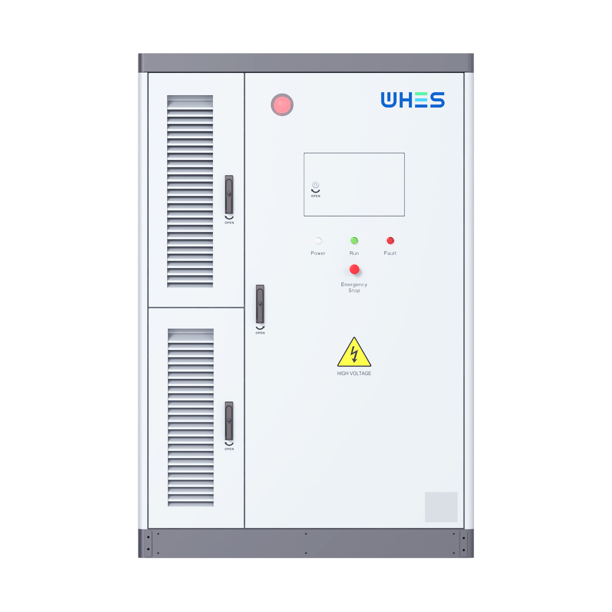
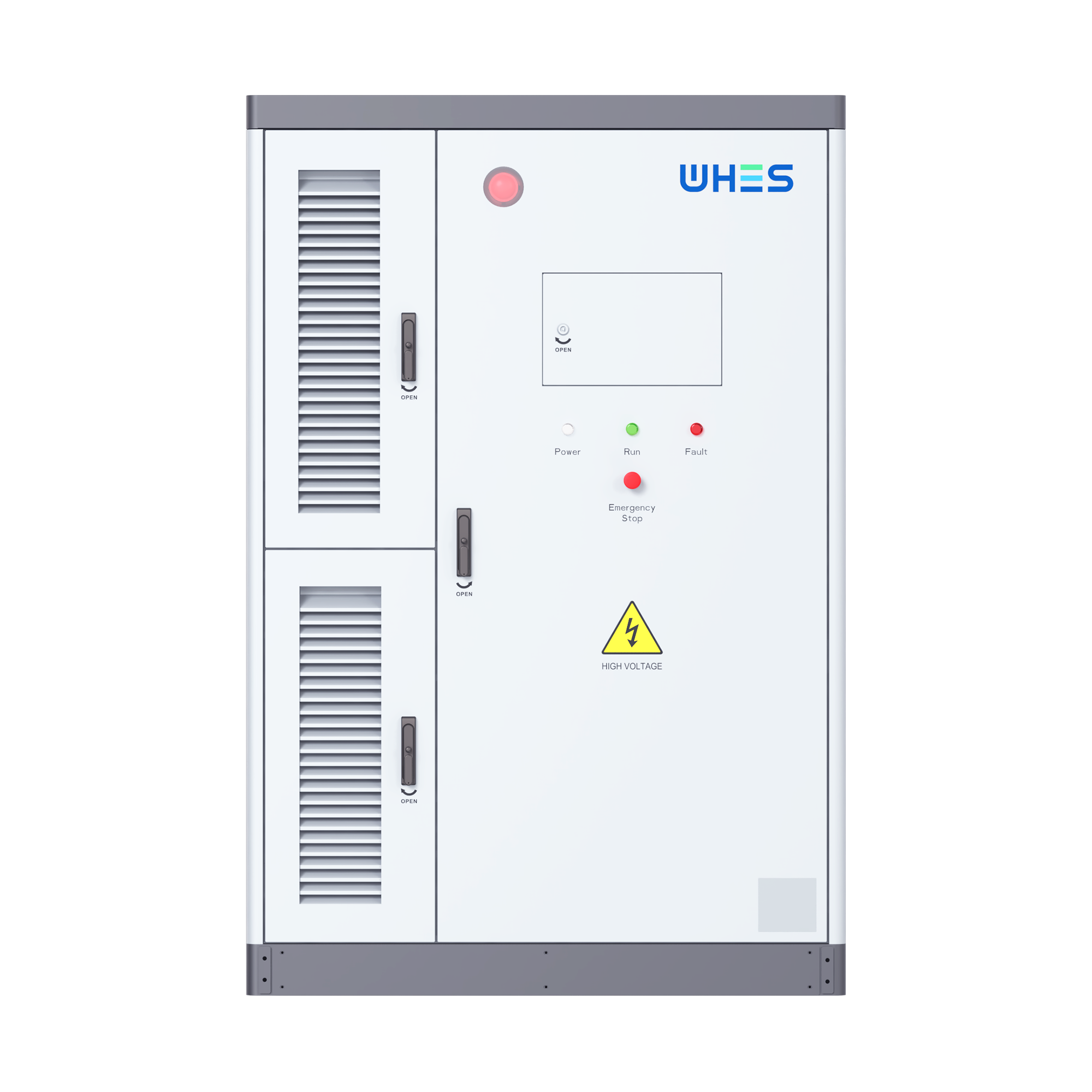
Start with a clear, repeatable framework — assessment, design, install, test, operate — and you remove guesswork. This piece lays out that sequence for high-voltage BESS containers and focuses on practical decisions owners and engineers face in real projects. If you’re evaluating integrated units, consider an all in one energy storage system as a baseline for footprint, inverter pairing, and factory-configured protections. The framework keeps safety, code compliance, and grid interface at the center so you don’t learn hard lessons in the field.
1. Site assessment & safety priorities
Begin with a site audit: access, crane capacity, ground conditions, proximity to public spaces, and existing switchgear. Map out medium-voltage (MV) and low-voltage routing early; neglect here adds days and cost later. Include thermal-risk zones and escape routes in your plan. Real-world anchor: recent grid crises — like the Texas winter storm of February 2021 — showed how emergency deployments and grid-edge storage must be sited with both safety and rapid accessibility in mind.
2. Design rules for electrical interfacing
Design the electrical interface around compatibility: DC bus architecture, inverter ratings, protective relays, and clearly defined point-of-interconnection (POI). Specify protection relay coordination and anti-islanding behavior to meet interconnection agreements. Keep tolerance tables for connector torque, cable ampacity, and SOC management in the commissioning checklist. Don’t assume an inverter will behave identically across vendors — verify control signals and telemetry mappings before installation.
3. Mechanical integration and container handling
Containers look simple, but mechanical works matter: lifting points, fork pockets, and enclosure grounding. Plan cable entries and segregate MV from auxiliary cabling to limit electromagnetic interference. Thermal management is equally critical — internal HVAC, heat exchangers, and fire separation must match the BMS and battery chemistry. Small teams often underestimate enclosure condensation risks — condition monitoring prevents corrosion and unexpected downtime.
4. Safety systems: fire, ventilation, and grounding
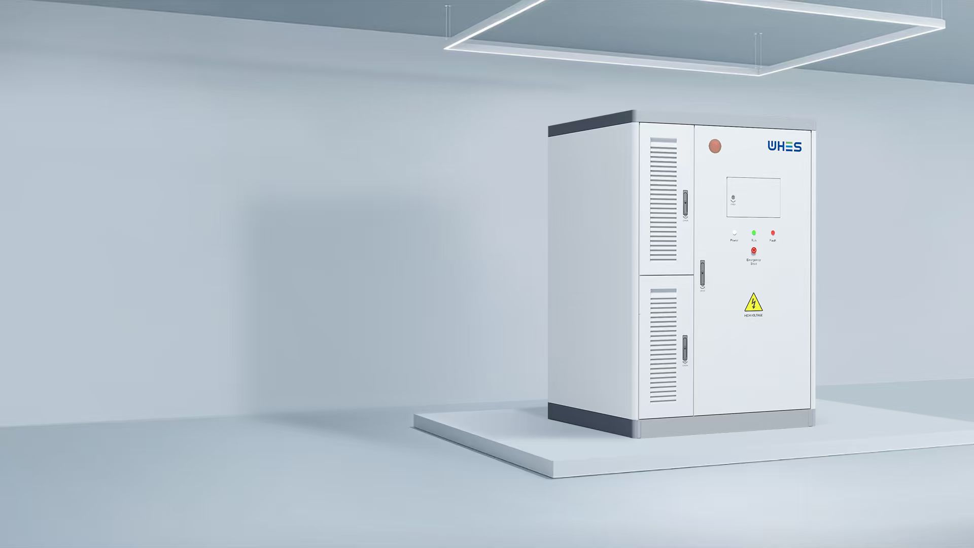
Install layered protections: forced ventilation, gas-detection or smoke detection tied to automated shutdown, and an approved fire suppression approach suited to lithium chemistries. Bonding and earthing must follow local electrical code and the interconnection utility’s requirements. Include clear isolation procedures and labeled lockout points for maintenance crews — isolation isn’t just a switch, it’s a tested sequence that reduces human risk.
5. Commissioning, testing, and operational readiness
Commissioning is where the framework proves itself. Run functional tests: protective relay trips, inverter sync, BMS alarm thresholds, and DERMS/SCADA telemetry. Perform a staged energization with documented test results at each step. Verify charge-discharge cycles, and validate that SOC reporting aligns with the BMS and grid operator expectations. Capture baseline performance so you can spot drift later — a simple log of initial round-trip efficiency saves debate down the road.
6. Augmenting capacity and modular upgrades
When you plan future expansions, design busbars, cable ducts, and mechanical clearances to accommodate extra modules. Standardize interconnects and control APIs so new packs or additional inverters can join the system without wholesale redesign. Consider factory-built modular options or systems labeled as an all in one solar battery system for predictable scale-out. Upgrades should be plug-compatible; if they’re not, expect rework and schedule slippage — and that will cost you.
7. Common mistakes and how to avoid them
Teams frequently trip over three issues: inadequate interconnection agreements, ambiguous maintenance responsibilities, and poor cable management. Avoid those by documenting ownership, specifying cable tray separations, and locking down protective coordination studies with the utility. Also—insist on real equipment trials with your chosen inverter and protection systems during FAT (Factory Acceptance Testing). Those tests catch the 80% of integration problems you’ll otherwise discover on day one.
8. Lifecycle operations: monitoring, maintenance, and safety drills
Set up continuous telemetry for cell groups, HVAC status, and protection events. Schedule quarterly inspections and an annual full discharge/charge verification test. Run emergency response drills with local fire services and your operations team — practical drills identify communication gaps that paperwork won’t. Keep firmware and BMS updates controlled and documented; untested firmware changes are a common source of unintended behavior.
Advisory: three golden rules for selecting tools and strategies
1) Prioritize proven interoperability — choose vendors with documented POI and relay coordination experience; compatibility reduces commissioning risk. 2) Design for serviceability — ensure access, spare parts, and standardized connectors; downtime is mostly avoidable if systems are maintainable. 3) Insist on measured performance baselines — require FAT and SAT results showing inverter efficiency, round-trip efficiency, and BMS alarm fidelity before acceptance.
When you align safety, interoperability, and maintainability in your framework, you shorten schedules and cut risk — and that’s precisely the value WHES brings as an integrated solution partner. WHES. —